CAN or Controller Area Network is a two wired half duplex high speed serial network technology. It is basically used in communication among different devices in a low radius region, such as in an automobile. A CAN protocol is a CSMA-CD/ASM protocol or carrier sense multiple access collision detection arbitration on message priority protocol. CSMA ensures each node must wait for a given period before sending any message. Collision detection ensures that the collision is avoided by selecting the messages based on their prescribed priority.
It provides signaling rate from 125kbps to 1 Mbps. It provides for 2048 different message identifiers.
It is ISO-11898 standard and makes use of the 7 layer Open Systems Interconnection model.
History:
It was developed by Robert Bosch in 1982 and officially released by the Detroit’s society of Automotive Engineers in 1986. The first car integrating CAN bus was manufactured by Mercedes Benz in 1992.
ISO 11898 Architecture:
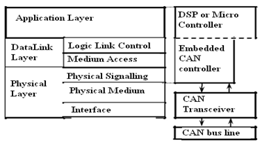
The layered architecture consists of three layers
- Application Layer: It interacts with operating system or the application of CAN device.
- Data Link Layer: It connects the actual data to the protocol in terms of sending, receiving and validating data.
- Physical Layer: It represents the actual hardware.
The standard CAN frame consists of the following bits:
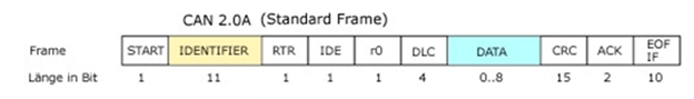
The standard CAN frame consists of the following bits:
- SOF- Start of Frame. The message starts from this point.
- Identifier: It decides the priority of the message. Lower the binary value, higher is the priority. It is 11 bit.
- RTR– Remote Transmission Request. It is dominant when information is required from another node. Each node receives the request, but only that node whose identifier matches that of the message is the required node. Each node receives the response as well.z
- IDE– Single Identification Extension. If it is dominant, it means a standard CAN identifier with no extension is being transmitted.
- R0– reserved bit.
- DLC– Data Length Code. It defines the length of the data being sent. It is 4 bit
- Data– Up to 64 bit of data can be transmitted.
- CRC– Cyclic Redundancy Check. It contains the checksum (number of bits transmitted) of the preceding application data for error detection.
- ACK– Acknowledge. It is 2 bit. It is dominant if an accurate message is received.
- EOF– end of frame. It marks end of can frame and disables bit stuffing.
- IFS– Inter Frame Space. It contains the time required by the controller to move a correctly received frame to its proper position.
5 Different message types are:
- Data Frame: It consists of arbitrary field, data field, CRC field and the acknowledge fields.
- Remote Frame: It requests for transmission of data from another node. Here the RTR bit is recessive.
- Error Frame: It is transmitted when a error is detected.
- Overload Frame: It is used to provide delay between messages. It is transmitted when the nodes become too busy.
- Valid Frame: A message is valid if the EOF field is recessive. Else the message is transmitted again.
CAN Physical Layer:
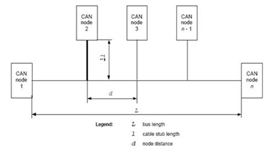
It consists of two wire serial link- CAN_H and CAN_L and their voltage levels It consists of two wire serial link- CAN_H and CAN_L and their voltage levels relative to each other determine whether a 1 or 0 is transmitted. This is differential signaling. The current flowing in each signal line is equal but opposite in direction, resulting in a field-canceling effect that is a key to low noise emissions. This ensures a balanced differential signaling which reduces noise coupling and allows high rate of transmission over the wires. Usually the wires are twisted pair cables with bus length of 40 m and maximum of 30 nodes. It is a shielded or un-shielded cable with a characteristic impedance of 120 Ohms.
Advantages of CAN:
- It reduces wiring since it is a distributed control and this ensures enhancing of the system performance.
- Many CAN chip manufactures provided the data link layer and the physical layer interfaced to the chip and all the software developer needs to do only is to develop the application coding.
- It provides the ability to work in different electrical environment and ensures noise free transmission.
- Traffic congestion is eliminated as the messages are transmitted based on their priority and it allows the entire network to meet the timing constraints.
- It provides for error free transmission as each node can check for errors during the transmission of the message and send the error frame.
Note: Image illustrations are taken from the internet source for better understanding.
